If preconstruction is the "brain" of the project and field technology is the "hands", then coordination is the "nervous system" that connects them. In the traditional construction model, coordination was often a reactive process—a sheet metal foreman solving a duct conflict by hammering it flat on-site. In the BIM era, coordination is a proactive, predictive science.
This guide dives into the technical mechanics of Model Coordination. We will move beyond the basic concept of "clash detection" to explore advanced strategies like Search Sets, Clearance Modelling, and the Macro-to-Micro workflow. We will examine how to elevate models to LOD 400 (Fabrication), turning the virtual model into a direct driver for CNC machinery. Finally, we will look at Installation Verification using laser scanning to ensure the physical reality matches the digital plan. This is where we stop drawing lines and start modelling components that can be manufactured, shipped, and installed with zero rework.
The Evolution of Coordination: From Light Tables to Laptops
To appreciate the sophistication of modern coordination, we must understand the friction it replaced.
The "Light Table" Era
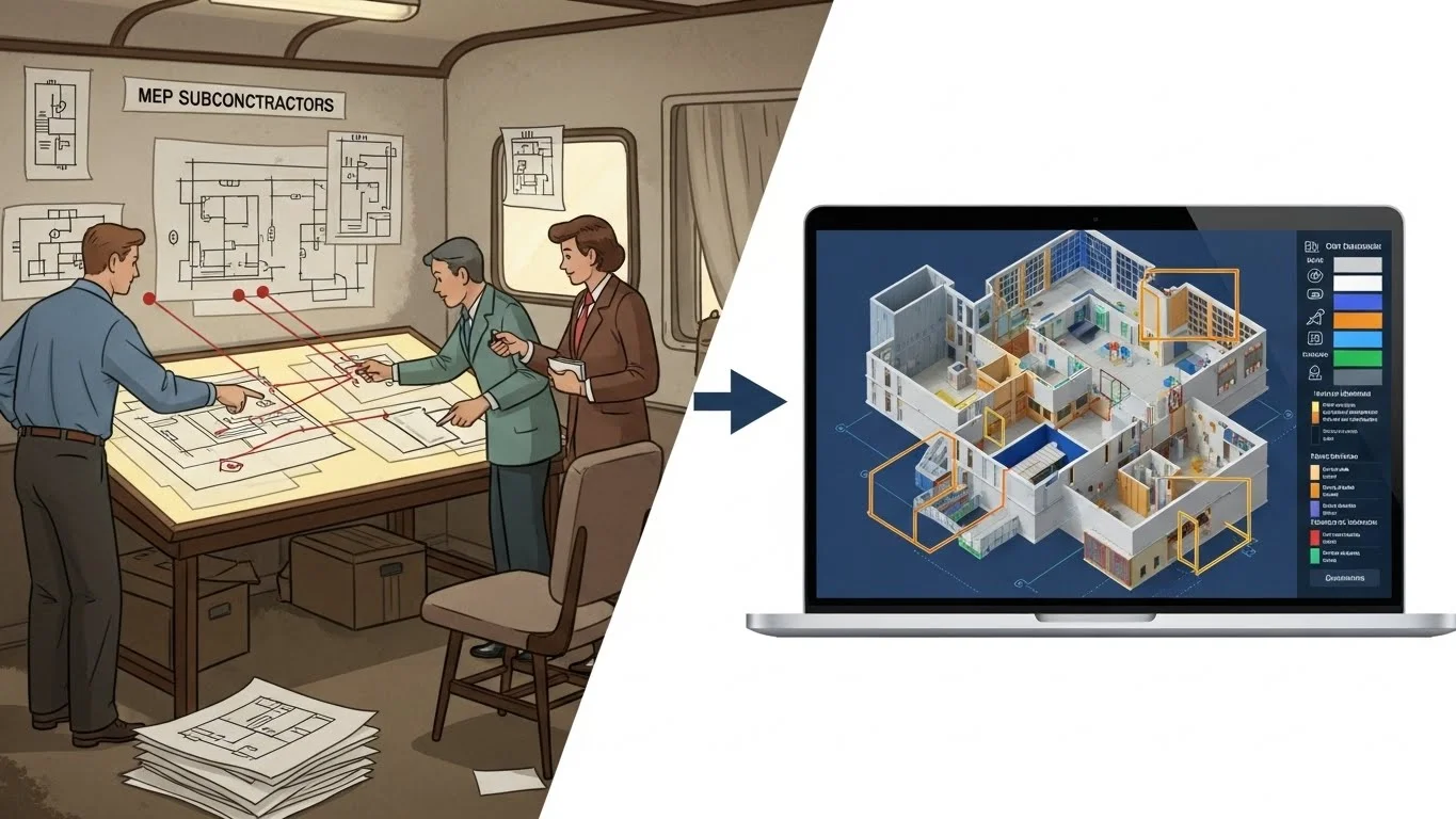
For decades, coordination was an analog process. The mechanical, electrical, and plumbing (MEP) subcontractors would draft their shop drawings on vellum or Mylar. They would physically meet in a trailer, stack their drawings on a light table, and look for "shadows" where lines crossed.
- The Limitation: This method was inherently 2D. It could catch a duct crossing a pipe on a plan, but it could rarely identify a vertical conflict—like a pipe running through a beam—until the crew was standing on a ladder with a core drill.
- The "Design Intent" Gap: Architects produced "design intent" drawings (single-line diagrams), leaving the "means and methods" to the subcontractors. This often resulted in a "first-come, first-served" mentality in the ceiling plenum, where the first trade to install claimed the best route, forcing others to make expensive diversions.
The Shift to 3D Composite Modelling
BIM changed the medium; more importantly, it changed the sequence. We now build the building twice: once virtually and once physically.
- The Federated Model: We no longer stack paper; we aggregate digital files (RVT, DWG, NWC) into a single "Federated Model" (typically in Navisworks or Solibri).
- Democratization of Data: In the light table era, only the foreman saw the coordination. In the BIM era, the coordination model is accessible to everyone. A pipe fitter can see exactly how their pipe weaves through the steel before they cut a single stick of unistrut.
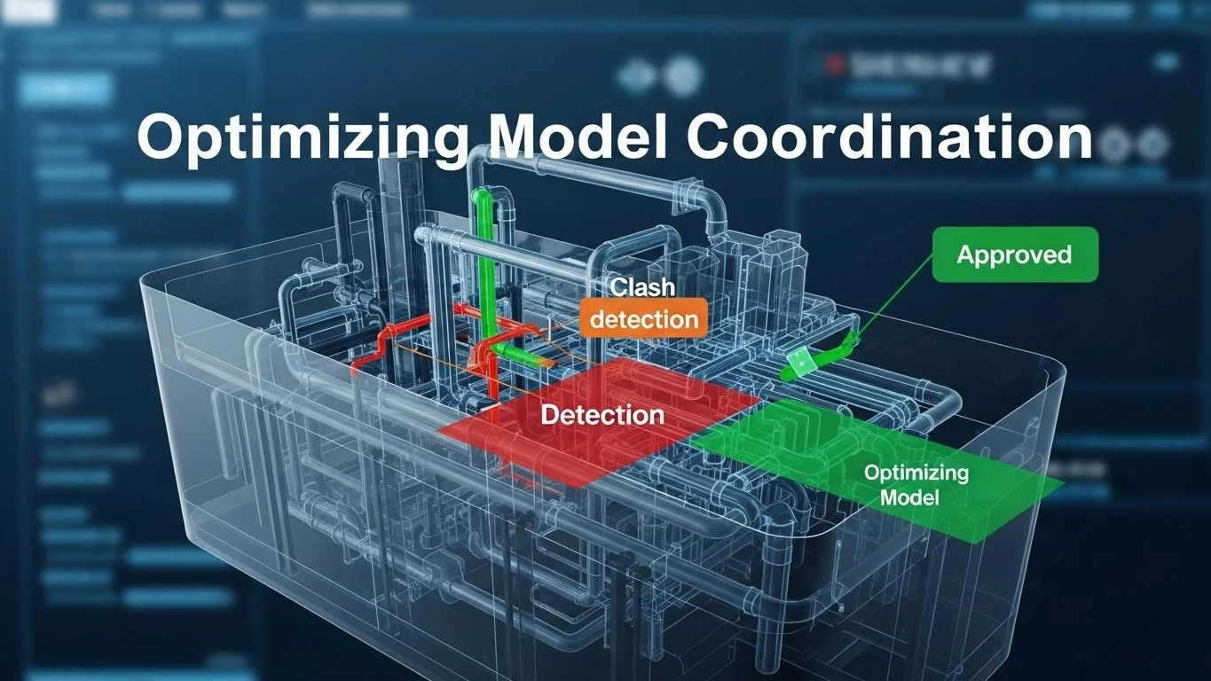
Advanced Clash Detection Workflows
Clash detection is the most well-known BIM use case, but it is often executed poorly. Many teams run a "lazy" clash test—selecting "All vs. All"—and are then paralyzed by 50,000 false positives. Effective coordination requires a surgical strategy.

1. The Macro to Micro Strategy
You cannot boil the ocean. Successful coordination follows a hierarchy of importance.
Macro Coordination (The "Big Rocks"): Before worrying about 1-inch conduit, you must resolve the major systems.
- Gravity Systems: Sanitary and storm pipes depend on slope. They cannot just "go around" an obstruction. They have the "right of way."
- Large Ductwork: Main trunk lines are massive and rigid. They consume the most volume in the plenum.
- Structure: Beams and columns are immovable constraints.
- Strategy: Run the first round of clashes solely between Structure, Gravity Pipe, and Large Duct. Ignore the small stuff. If the main trunk line hits a beam, that is a critical issue that stops the job.
Micro Coordination (The "Gravel"): Once the macro systems are locked, you layer in the flexible systems.
- Pressure Piping: Water supply and hydronic heating pipes can route around obstacles using 90 or 45-degree elbows.
- Conduit and Fire Protection: These are the most flexible systems (often bent by hand or utilizing flex-drops).
- Strategy: Do not waste time clashing small conduit vs. small conduit. The field crews can resolve those minor conflicts easily. Focus on where these small systems hit the "Big Rocks."
2. Search Sets vs. Selection Sets (The "Golden Rule" of Navisworks)
A common mistake in Navisworks is using manual "Selection Sets."
- The Mistake (Selection Sets): You manually click on 50 beams and save them as "Level 1 Beams." The next week, the engineer adds 10 new beams. Your selection set is now outdated because it doesn't include the new elements. You are clashing against old data.
- The Solution (Search Sets): Search Sets are dynamic queries based on data
properties.
- You create a query: Find all items where "Category" = "Structural Framing" AND "Level" = "Level 1".
- When the model updates and new beams are added, the Search Set automatically grabs them because they meet the criteria. This ensures your clash tests are always comprehensive and maintenance-free.
3. Clearance and Maintenance Modelling
Clash detection is not just about physical collisions; it is about operability. A variable air volume (VAV) box might fit in the ceiling, but can the facility manager open the access door to change the filter?
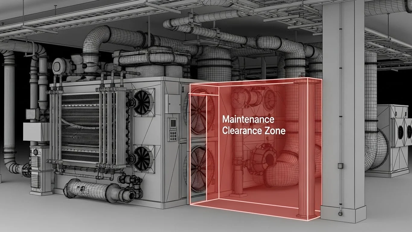
- Modelling "Blobs": We model invisible "clearance zones" (often translucent red boxes) in front of electrical panels, valve handles, and equipment access doors.
- Soft Clashes: We run a clash test of "Structure vs. Clearance Zones." If a beam hits the invisible box, it registers as a clash. This guarantees that the facility team will not have to demolish a wall just to service a breaker panel 5 years later.
4. Grouping and Management
Running a test might yield 500 clashes, but they might all be caused by one issue—e.g., a single duct run crashing through 20 floor joists.
- Clash Grouping: The coordinator must group these 20 clashes into a single issue: "Lower Main Duct trunk." This reduces the "Clash Count" from 500 to 1, providing a psychologically manageable number for the team to attack.
BIM for Fabrication (LOD 400)
The goal of coordination is not just a pretty picture; it is prefabrication. We want to move labour from the dangerous, uncontrolled job site to the safe, controlled environment of a shop. This requires moving the model from LOD 300 (Design Intent) to LOD 400 (Fabrication).
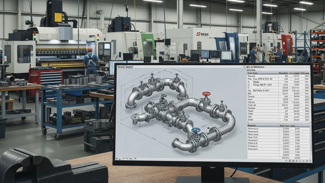
Engineered-to-Order (ETO) Components
LOD 400 models contain the exact logic of fabrication.
- Sheet Metal (The Spool Sheet): A design model shows a continuous duct. A fabrication model breaks that duct into 5-foot "spools" (sections) based on the sheet metal coil size. It adds flanges, hangers, and turning vanes. These files are sent directly to the plasma cutter.
- Mechanical Piping: Instead of welding pipe on a ladder, the contractor spools the system in the model. They create detailed isometric drawings for the shop. The pipe is cut, welded, and pressure-tested in the shop, then delivered to the site in 20-foot assemblies that simply bolt together.
The "BIM-as-Built" Logic
In this workflow, the model is the order form.
- CNC Integration: The geometry from the BIM software (e.g., Revit/CADmep) is exported to standard file formats (like .MAJ or .PCF) that drive Computer Numerical Control (CNC) machines. The machine reads the file and cuts the steel or pipe to the exact millimetre derived from the coordinated model.
- Waste Reduction: Because the parts are nested and cut by computer, scrap waste is virtually eliminated. This is the ultimate realization of Lean Construction.
Installation Verification: Closing the Loop
The best model in the world is useless if the field team installs it in the wrong place. We must verify that the physical reality matches the digital plan. This is where Laser Scanning (LiDAR) enters the coordination workflow.
The Problem: Tolerance Drift
In a digital model, a column is perfectly vertical. In reality, concrete sags, steel twists, and humans make measuring errors. If we prefabricate a $100,000 piping rack based on the perfect model, but the concrete wall is 2 inches out of plumb, the rack won't fit.
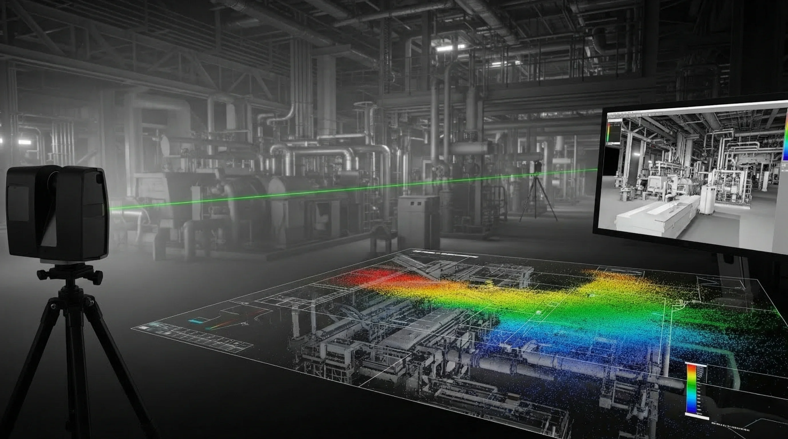
Laser Scanning (Scan-to-BIM)
Laser scanning captures the "truth" of the site. A scanner shoots millions of laser points per second, creating a "Point Cloud"—a highly accurate digital replica of the physical space.
- Pre-Pour Scanning: Scan the rebar and sleeves before concrete is poured. Overlay this scan on the model to verify that every sleeve is in the correct location. If a sleeve is missed, you can fix it in minutes before the concrete truck arrives, rather than spending thousands to X-ray and core drill later.
- Floor Flatness Analysis: Scan the wet concrete or the finished slab. The software generates a "heat map" showing high and low spots. This allows the team to grind down high spots or use self-levelling compound on low spots before flooring installation begins, preventing warranty claims.
Case Study: Intraoperative MRI Suite
The "BIM and Construction Management" text highlights a critical case study involving an intraoperative MRI suite.
- The Challenge: An MRI machine is a massive magnet. It hangs from a steel rail system that allows it to move between the operating room and the diagnostic room. The tolerance for these rails is incredibly tight—fractions of a millimetre. If the rails are not perfectly parallel, the magnet will jam.
- The Solution: The team did not rely on tape measures. They used a
laser
scanner to capture the existing steel structure.
- They brought the Point Cloud into the BIM software.
- They modelled the new rail system to fit the actual (slightly imperfect) steel, not the theoretical design.
- During installation, they scanned the rails again to verify they were within the sub-millimetre tolerance required by the MRI manufacturer.
- The Result: The rails were installed perfectly on the first try. The MRI machine was commissioned without delay. Without scanning, the team would likely have faced weeks of rework and "shimming" to get the rails straight.
Detailed Coordination Management: The "Clash Meeting"
Technology is only 20% of the solution; the other 80% is sociology. The Weekly Coordination Meeting is where the battle is won or lost.
The Rules of Engagement
To prevent meetings from becoming 4-hour shouting matches, strict protocols are needed.
- The "24-Hour Rule": Models must be uploaded 24 hours before the meeting. The BIM Manager runs the clash detection overnight. The report is sent to all subcontractors the morning of the meeting.
- The "Accountability Seat": When a clash is reviewed (e.g., Duct vs. Pipe), the software shows who owns the object. The question is simple: "Bob, your duct is hitting Alice's pipe. Can you move up?"
- The "Model-First" Culture: If a subcontractor says, "I can't move that, I've already fabricated it," but the model showed a clash for three weeks that they ignored, they are responsible for the rework cost. The model is the contract.
The Sign-Off Model
Once coordination is complete for a zone, the team must "freeze" the model.
- Digital Sign-Off: Each subcontractor signs a document stating, "This model represents what I will install."
- The "Red Zone": In the software, the status of that zone is changed to "Locked." No one is allowed to move an object in a locked zone. This prevents the "drift" where a plumber moves a pipe to fix a new issue and accidentally creates a clash in a zone that was already solved.
Conclusion: The "Single Source of Truth"
Optimizing model coordination is about establishing a "Single Source of Truth." In the past, the truth was fragmented across a thousand paper drawings. Today, the Federated Model is the truth.
By moving from reactive "field fixes" to proactive Search Sets and Macro-to-Micro analysis, we clear the path for the builders. By elevating to LOD 400, we unlock the speed of prefabrication. And by closing the loop with Laser Scanning, we ensure that our digital promises are kept in the physical world.
This level of coordination requires discipline. It requires a BIM Manager who is not just a software jockey, but a diplomat and a construction strategist. But the reward is a project that fits together like a Swiss watch—quiet, efficient, and devoid of the chaotic "noise" of rework.


